
Introduction
The Progressive Learning Platform (PLP) utilized on the PLP Board provides a unique learning platform designed to be simple, open, and useful for education.
This document serves as a detailed guide for developers for the Progressive Learning Platform System on a Chip (SoC).
Software Tools (PLPTool)
PLPTool is the software suite for the Progressive Learning Platform that incorporates an assembler, a board simulator, and a board programming interface.
Getting PLPTool
Always make sure to run the latest version of PLPTool. Not only does it offer new features or bug fixes, this manual is also tailored to the newest version and certain sections may not be applicable to older versions.
The latest version of PLPTool (5.2) is available on GitHub. Download the .zip file on the right side. It will contain the following directories:
- images - misc images for use by PLPTool
- misc - miscellaneous files
- resources - where you should find everything for PLPTool
- hw - Hardware images for the CPU (for all 3 supported boards)
- sw - Software tools (including PLPTool), example programs, and the software libraries
- PLPTool - PLPTool (Windows 32/64-bit, and Mac/Linux)
- libplp - PLP Software Libraries
- examples - Example Programs
- web - files used for the plp website
Running PLPTool
There are several requirements for running PLPTool:
- A Java Runtime Environment (JRE) that compiles with at least Java 2 Platform SE 5 (1.5)
- If you aren’t sure if you meet this requirement, or you do not have a compatible JRE, you can download the latest version here.
- RXTX Library for Serial Communication
- If you are using Windows, RXTX Library is bundled with PLPTool.
- If you are using Mac/Linux, you must install the library manually.
- If you are running Windows, you must know whether it is 32-bit or 64-bit.
- To do this, press the “Start” button, right click on “Computer”, and click “Properties”. From there, you should see either a 32-bit or 64-bit system type.
Once the above requirements are met, you are ready to run PLPTool.
First, you must extract the .zip file downloaded earlier containing PLPTool. After that, navigate to /sw/PLPTool/.
To run PLPTool:
- If you are using Windows 32-bit, you need to run the batch file PLPToolWin32.bat.
- If you are using Windows 64-bit, you need to run the batch file PLPToolWin64.bat.
- If you are using Mac/Linux, you must use the Command Line to launch PLPTool.
- You can also do this in Windows.
Launching PLPTool with the Command Line
In order to launch PLPTool, open a terminal (or Command Prompt) and navigate to where you previously extracted the PLP .zip file. Once you get to the PLP folder, navigate to /sw/PLPTool. From there, you can launch PLPTool with several options.
- To launch PLPTool:
- For Windows 32-Bit, type:
PLPToolWin32.bat - For Windows 64-Bit, type:
PLPToolWin64.bat - For Mac/Linux, type:
java -jar PLPToolStatic.jar
- For Windows 32-Bit, type:
- To open a .plp project with PLPTool:
- For Windows 32-Bit, type:
PLPToolWin32.bat <.plp file to open> - For Windows 64-Bit, type:
PLPToolWin64.bat <.plp file to open> - For Mac/Linux, type:
java -jar PLPToolStatic.jar <.plp file to open>
- For Windows 32-Bit, type:
- To list the source files contained in a .plp file, type:
java -jar PLPToolStatic.jar -plp <.plp file>
The -plp <plpfile> command can also take additional arguments that can be used to manipulate the project file without launching PLPTool. These additional arguments are:
| Command Line Argument | Description |
|---|---|
-c <asm 1> <asm 2> … |
Creates <plpfile> and imports <asm 1>, <asm 2>, … to the project |
-p <port> |
Programs <plpfile> to the serial port |
| -a | Performs an assembly of the source files inside <plpfile> |
-i <asm 1> <asm 2> … |
Imports <asm 1>, <asm 2>, … into <plpfile> project file |
-d <directory> |
Import all files in <directory> to the <plpfile> project file |
-e <index> <file> |
Exports the source file with the index <index> as <file> |
-r <index> |
Removes the source file with the index <index> |
-s <index> |
Set the source file with the index <index> as the main program |
-m <index> <new index> |
Set <new index> for the source file with the index <index> |
PLPTool Graphical User Interface (GUI)
PLPTool starts in the development environment view, displaying the current open project, files in the project, and a status/console window. From here, you can import, remove, and create new assembly files, assemble the current project, go into simulation mode, and program the PLP board.
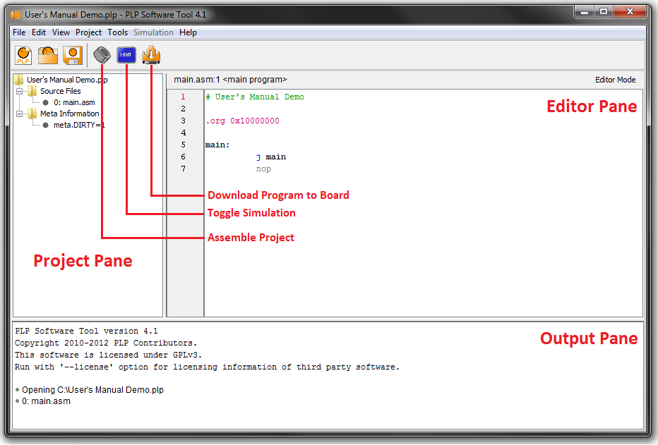
The Project Pane contains all the source files in the project. The Editor Pane displays the contents of the currently open source file. The Output Pane displays status, warning, and error messages.
Simulator
PLPTool includes a cycle-accurate simulator that can be accessed through the GUI or via a command-line argument.
- To launch the simulator from within PLPTool, press the “Simulator” toggle button.
- To launch a text-based simulator from the command line, type:
java -jar PLPToolStatic.jar -s <.plp file>
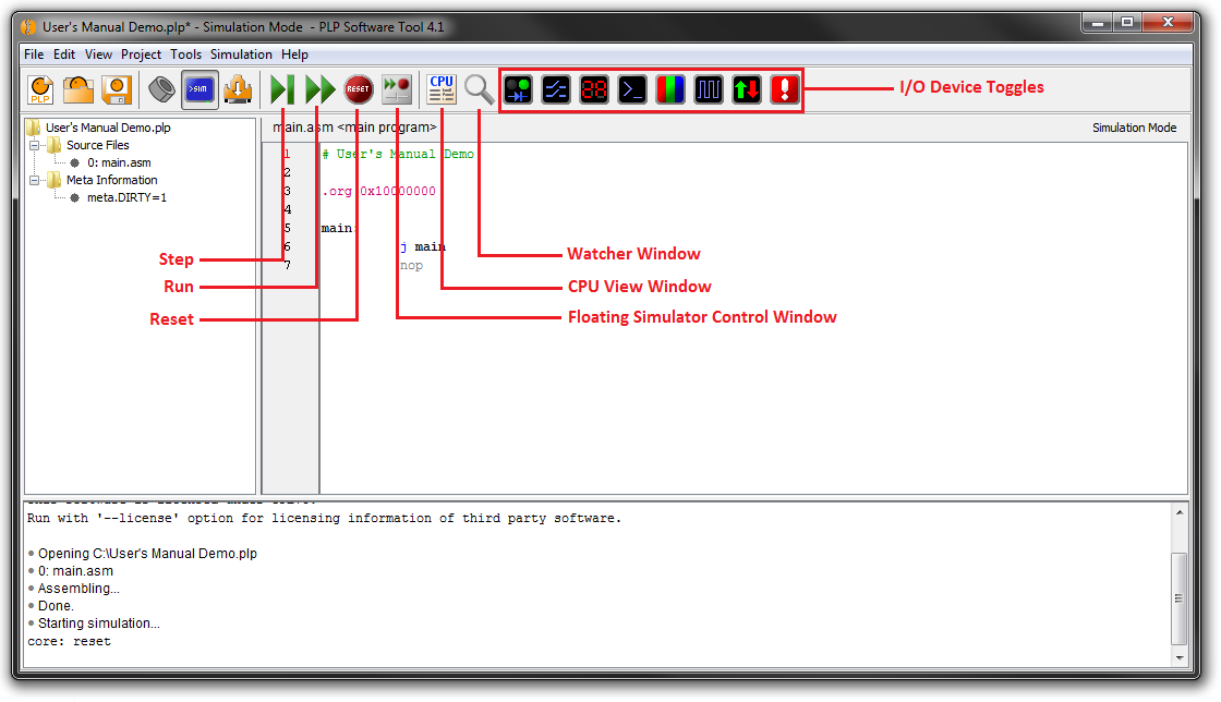
Simulation mode adds additional controls to the GUI window.
- The first three buttons are the the single cycle increment (step), run, and reset buttons.
- Step (F5) will advance the simulation by one cycle.
- Run (F7) will continuously run the simulation.
- Reset (F9) will return the CPU to the reset state, as well as reset all the registers to zero.
- The Floating Simulator Control Window allows you to stop and start/step the simulation, as well as control the step size.
- The CPU View button will display the CPU window where you can view and modify register file contents, see disassembly listing, and access the debug console.
- The Watcher Window button will display a window that allows the user to monitor the content of individual register addresses and buses.
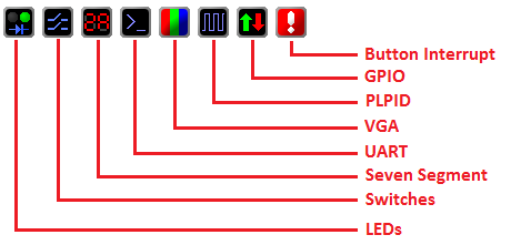
I/O Device Toggles
In addition to the step, run, reset, floating simulator control, CPU view, and Watcher window buttons, there are eight input/output (I/O) device toggles that will appear.
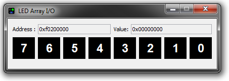
LEDs
Pressing the LEDs toggle button will bring up the window shown below. It displays the LEDs that are currently lit as a result of your code. It also displays the memory address of the LEDs, as well as the value stored at that location.
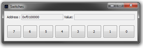
Switches
Pressing the Switches toggle button will bring up the window shown below. It displays an interactive window that allows you to select which switches you want to toggle on or off. It also displays the memory address of the switches, as well as the value stored at that location.
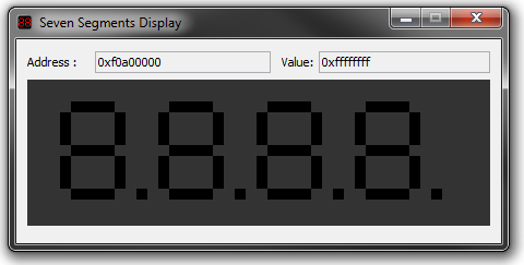
Seven Segment Displays
Pressing the Seven Segment Displays toggle button will bring up the window shown below. It displays the segments currently lit on the seven segment displays. It also displays the memory address of the seven segment displays, as well as the value stored at that location.
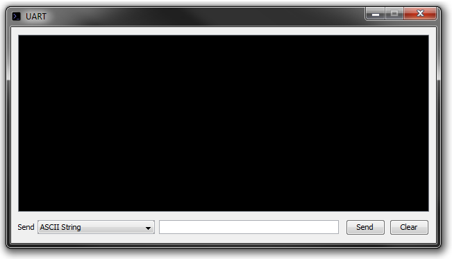
UART
Pressing the UART toggle button will bring up the window shown below. It displays a window that allows you to send and receive data through an emulated serial port. It gives you three options of sending the data:
- ASCII String
- 1-byte raw
- Space-delimited raw
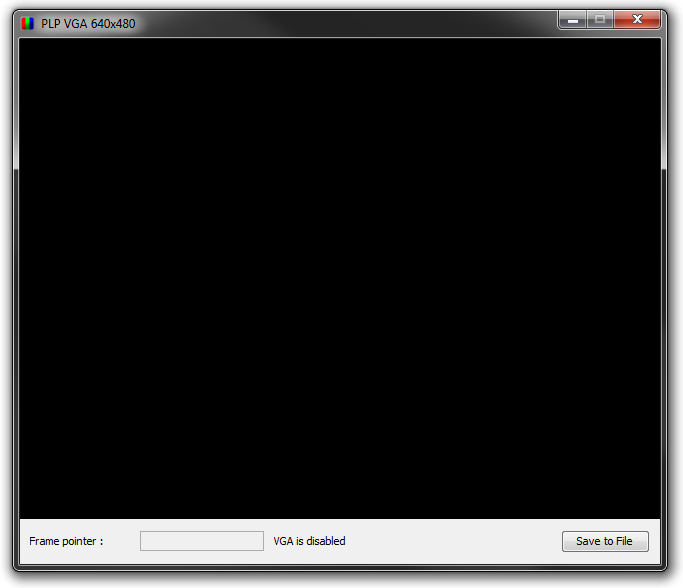
VGA
Pressing the VGA toggle button will bring up the window shown below. It displays a VGA window with a resolution of 640x480, where an image is displayed if your code writes to the VGA’s memory address. It also displays whether VGA is enabled or disabled, as well as the current frame pointer.
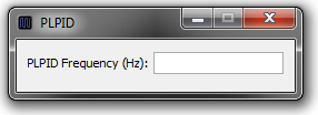
PLPID
Pressing the PLPID toggle button will bring up the window shown below. It displays a window that shows the frequency of the PLP Board you are using. This is useful for implementing a wait routine within your program.
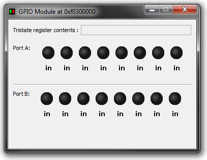
GPIO (General Purpose Input/Output)
Pressing the GPIO toggle button will bring up the window shown below. It displays an interactive window with the 16 enabled GPIO ports (separated into Port A and Port B) for the emulated PLP Board. It also displays the contents of the tristate register.
Button Interrupt
The Button Interrupt toggle triggers a jump in the program to your code’s interrupt service routine (ISR). No window is displayed.
Breakpoints
A breakpoint is a line in the program where execution halts. This useful for testing and debugging.
The breakpoint in PLP can be set by double-clicking the line number where you want the program to halt. However, a breakpoint can only be set on a line where an instruction is present, meaning it cannot be set on a blank line.
To clear an existing breakpoint, you can double-click on the line number where the breakpoint is located. You can also clear all the breakpoints by going to Simulation on the menu bar, and clicking the Clear Breakpoints option. This can also be done by pressing Ctrl + B.